
Conduit Bending Calculator in 3D
Choose an offset, a 90-degree stub-up, or a three-bend saddle. See the finished conduit in 3D and switch to the straight layout to read the bend marks before the shape changes.
Explore This Calculator
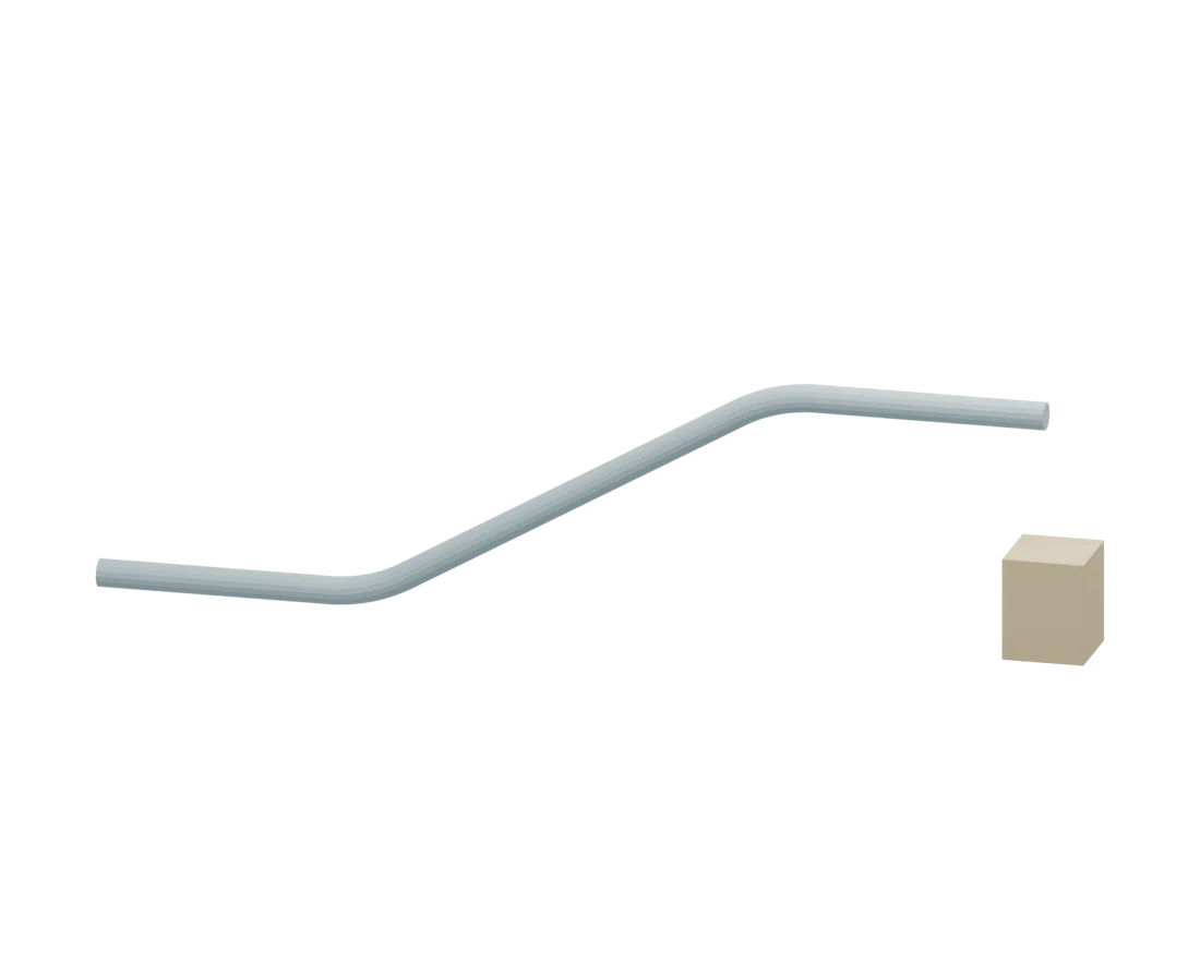 Drag to Rotate
The finished bend uses circular centerline arcs and your model radius. Offset height is measured between parallel centerlines.
The Offset Multiplier Table
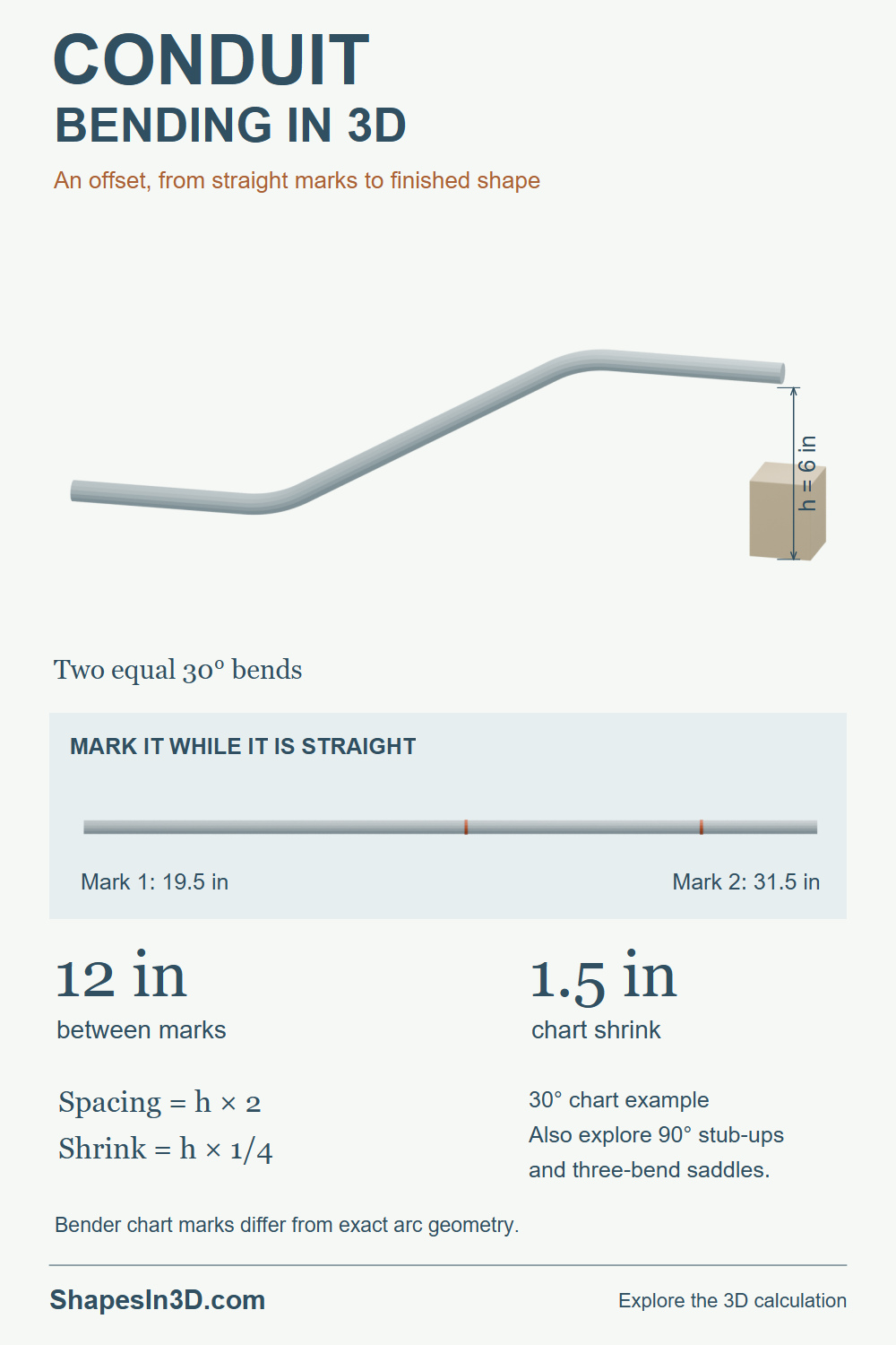
For an equal two-bend offset, multiply the offset height by the selected angle’s multiplier to find the distance between bend marks. Multiply the height by the shrink constant when approaching an obstruction.
Mark spacing = height × multiplier
Chart shrink = height × shrink constant
The chart values are rounded practical layout factors. They are intentionally kept separate from exact circular-arc calculations.
| Equal Offset Angle | Published Multiplier | Shrink per Unit Height |
|---|---|---|
| 10° | 6× | 0.0625 |
| 15° | 3.86× | 0.125 |
| 22.5° | 2.6× | 0.1875 |
| 30° | 2× | 0.25 |
| 45° | 1.4× | 0.375 |
| 60° | 1.2× | 0.5 |
From Straight Marks to a Finished Bend
For an approaching offset, the second mark is the obstruction distance plus shrink. The first is one mark-spacing earlier. A negative first mark means there is insufficient distance from the conduit end.
Inspect the Curve Itself
The centerline radius controls the size of each smooth bend. Changing this model radius does not silently change the bender’s published mark method or its stub deduct.
6 in offset × 2 = 12 in between marks
90° Stub-Up
Mark position = finished stub height − the deduct printed for your bender and conduit size. The initial 5 in deduct is an editable example, not a universal value.
Three-Bend Saddle
The center mark uses the saddle notch alignment and the outer marks use the tool’s offset alignment. Match the chart method to the actual tool; centerline geometry alone does not locate every shoe mark.
Offset and saddle marks use rounded hand-bender chart constants. The smooth 3D shape uses the entered centerline bend radius, so its exact tangent distances can differ from chart marks. Stub deduct depends on the actual bender, size, and conduit. Confirm those markings and the permitted bend radius before laying out work.
Featured Image
The finished offset is paired with its straight mark layout and the multiplier and shrink calculations.
Pin ItView Featured Image